Trenching operations are never “ordinary.” Accidents are never expected. But they can be anticipated and prevented. To be forewarned is to be forearmed. Geotechnical investigation of the soil to be excavated during the trenching operation provides the first warnings that there could be a problem with trench stability. Engineering analysis is the best defense against disaster once potential problems are uncovered. Using both sources of information allows the contractor to choose the most appropriate method of protecting his crew from potentially catastrophic earth movement. And even the most diligent investigation and thorough analysis will not discover every danger. Therefore, a trenching contractor must be ready to quickly set up additional safeguards and modify his trenching operations to further ensure site safety. In order to meet this goal, both the contractor and his crew need to be thoroughly trained in the installation and use of protective measures that prevent sidewall cave-ins or protect workers should one occur.
So, what can go wrong? Put simply, cave-ins and sidewall collapses pose the gravest dangers to workers down in the trenches. They are far more likely to cause fatalities than any other occurrence on a job site (falls, falling loads, hazardous atmospheres, vehicle accidents, fires or explosives, and incidents involving mobile equipment). Each year America experiences dozens of fatalities and hundreds of injuries due to trench collapse. And tragically, these are all preventable.
Types of Trench Cave-Ins
The engineer designing the trenching system and the contractor performing the excavation need to work closely together to determine the types of trenching to be performed based on the various types of soils to be encountered along the trench alignment. But the types of soil are not the only concern. For example, trenching performed next to highways needs to take into account the surcharge loads and vibrations from truck traffic. Furthermore, the type of trench failure needs to be anticipated and planned for, with each type of trench failure corresponding to a specific type of soil failure.
A layered soil failure results when a trenching operation exposes several layers of different soils, with each soil layer having different strength characteristics. Specifically, this type of failure occurs either in an underlying weak soil layer or directly in an overlying weak soil stratum that is subject to a surcharge load. Such a surcharge load can be either the dead load from a stockpile of borrow soil placed too close to the edge of the trench or both the live and dead loads from active equipment operating near the trench.
Once exposed to wind and air, previously buried soil can be subject to drying out or even desiccation if exposed long enough. The act of losing moisture can reduce the cohesive strength of the soil, creating a weak spot that could trigger a sidewall failure. Since different soils respond to desiccation differently (with clay soils even propagating distinct desiccation cracks and fissures), variable soils can result in distinct weak points associated with the driest soils. For this reason, the contractor or the project engineer needs to test soil consistency and determine the characteristics of the different soils.
Some weak points occur naturally, without the need for subsequent exposure desiccation. These are pockets of soft and very soft clay or cohesionless pockets of sand or gravel. The unconfined strengths of clays can vary considerably. Trenching can also remove large objects if the site is located in a rock-strewn soil environment. Removal of a large object that straddles the limits of the trench can result in the creation of a large void in the sidewall that cuts back into the wall’s face. Whether obvious or hidden, the exposure of weak points can lead to trench wall collapse due to the lack of foundational support for the overlying soil.
The shape of the failure envelope (the surface through the soil defining the bottom of the soil mass mobilized by the sidewall failure) comes in two kinds: wedge failure and rotational failure. Wedge failure follows a straight line through the soil, typically along the boundary between two different soil strata. This boundary is often at a steep dip into the trench so that the overlying soil can slide into the trench in an angular direction. This situation becomes potentially critical in the presence of equipment operations and traffic vibrations.
By contrast, rotational failure occurs along a curved or circular failure plane. The starting point for the curved surface is either a weak point at the toe, an applied load at the top surface, or another weak point at the top such as a desiccation crack. Instead of movement along a clearly defined plane, rotational failure occurs around a mathematical center point (typically located above the physical trench) that acts as the pivot around which the soil rotates as it moves. Rotational failure is the most common type of failure mode in uniform, homogenous soils that lack a pre-existing potential failure plane.
The Mechanics of Trench Failure
There are multiple causes of trench collapse, and failure expresses itself in either straight wedge or rotational arc modes. To determine the potential for failure requires engineering analysis to determine the trench wall’s factor of safety against either type of failure.
The potential for rotational slope failure is evaluated by circular arc analysis. The actual failure surface is approximated by the segments of an arc of a circle (as represented in a two-dimensional cross section of the failure slope). The circular arc is centered on a point in space somewhere above the slope. The analysis of the potential for rotational slope failure involves the examination of multiple center point locations and arc radii.
The potential driving moment (the potential cause of overturning and slope failure) per unit width about the center point is the algebraic sum of the moments due to the weight of the slope’s soil mass, the horizontal and vertical components of water pressure acting on an inundated slope surface, and any other external loads acting on the driving mass. The weight of the soil is resolved using vectors into tangential components acting along/parallel to the potential failure arc segments and into normal components acting perpendicular to the failure arc segments. It is the tangential components that produce the driving force leading to overturning and slope failure. The perpendicular components act to create resisting forces resulting from the internal friction angle of the soil.
The potential resisting force (acting to prevent overturning and slope failure) per unit width about the center point is the algebraic sum of the moments due to the soil’s internal friction angle and cohesion. The resisting forces generated by the soil’s internal friction angle are dependent on the magnitude of the perpendicular weight component of the soil mass. Cohesive strength is an inherent soil characteristic. These slope stability calculations are typically performed by a computer program. The program determines the worst-case factor of safety for a number of center point locations and arc radii.
The potential sliding failure of a wedged mass of soil, the driving block, is resisted by the friction force acting along its bottom final cover soil/geosynthetic interface, and by a resisting force (if any) at the toe of the driving block. The force acting to cause potential sliding failure is the shear component of the driving block’s weight. However, unlike the curved failure plain of a rotational failure, these forces are resolved directly along the straight failure cut of the bottom of the soil wedge. As with the rotational failure mode, the factor of safety is typically calculated by a computer program. The program, in this case, determines the length and angle of the failure plane with respect to the horizontal.
In both cases, the factor of safety against failure is found by dividing the total resisting forces (toe and shear friction) by the total shear driving force of the soil weight. The minimum factor of safety required can depend on local conditions. A typical factor of safety of 1.5 is required for static, long-term, or permanent conditions; 1.2 for temporary conditions or when active dynamic loads are applied; and 1.0 for seismic conditions where an earthquake load impacts an open trench.
Mitigating Trenching Dangers
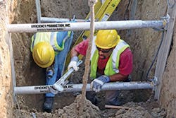
To minimize the inherent dangers of trenching operations, every trench deeper than 5 feet requires a protective system. Shoring is a common method of protection against trench sidewall collapse. Shoring involves the bracing of the trench sidewall to prevent collapse. There are several methods of doing so:
- Hydraulic shoring involves the use of hydraulic pistons to force outward against the sidewalls, providing active resistance pressure. Typically, they push sheets of steel plate or reinforced plywood called “FinForm.”
- Steel and plate shoring involve the use of I-beams driven into the ground at regular intervals along the toe of the trench sidewalls. Steel plates are then slid between them and the trench wall. If plywood is used instead of steel plates, they are called “soldier boarding.”
- Soil nailing reinforces trench sidewalls by the insertion of steel reinforcing bars into the sidewall at a downward angle. These are installed in predrilled holes of a depth necessary to ensure stability and then are grouted in place.
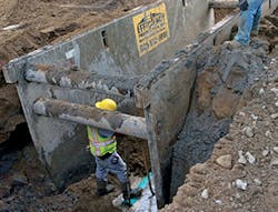
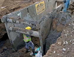
Shielding is another method of protection, but should not be confused with shoring. Shoring actively strives to prevent trench collapse while shields only provide protection for workers should collapse happen. Shielding is cheaper, but shoring is safer. Shields can be either trench boxes or trench sheets. Made of aluminum or steel, they are typically dragged along with the workers and provide cover for their immediate work area. For emergency trenching operations (to address utility failures, structural collapse, etc.), easily available mobile shielding may be more than sufficient and cost-effective given the time restraints required by the operation.
Safe Trenching Operations and Practices
In addition to active protection methods such as shoring and shielding, the configuration of the trench itself can be modified to improve safety. By definition, rock trenching is performed with safe vertical cuts. The most stable Type A soils can have a slope angle of 3/4-horizontal to 1-vertical ratio (a 53-degree angle). Type A soil can also be benched to create a stair-step cut on the trench side so that the overall slope is equivalent. In this case, the overall slope is achieved with 5-foot vertical cuts alternating with 4-foot-wide horizontal benches. Less stable Type B soils require a cut of 1-horizontal to 1-vertical ratio (a 45-degree angle). Type B soil can also be benched with 4-foot vertical cuts alternating with 4-foot-wide horizontal benches to achieve the overall 45 degrees. The least stable Type C soils the slope must be no steeper than 1.5 horizontal to 1 vertical (a 34-degree angle). This angle may be further affected by the presence of water saturation and seepage. Type C soils can never be benched.
Often overlooked but easily the most important safety factor is the human element—especially the combination of common sense and competency. Anyone with common sense should avoid entering an unprotected or improperly excavated trench, period. And any protective system in trenches cut more than 20 feet in depth should be analyzed and designed by an experienced registered professional engineer.
Which brings us to competency. OSHA regulations require daily inspections of trenches by a competent person prior to workers entering into the trench to perform work. A competent person is defined as one who has the knowledge and experience to identify existing and predictable hazards or working conditions that are hazardous, unsanitary, or dangerous to employees and who is authorized to take prompt corrective measures to eliminate or control these hazards and conditions. This competent person is trench safety’s first line of defense.
Means of safely accessing and egressing a trench must be provided no matter how safe the trench appears. These include ladders, steps, and ramps that can allow for quick and safe movement of personnel. They must be provided for any trench deeper than 4 feet and be located along the trench at 25 feet intervals from all workers. The ladders must extend 3 feet above the trench edge for safe ingress/egress.
In addition to inspecting a trench at the start of each work shift, several other common-sense precautions should be taken. Inspect the trench after a significant rainstorm for dangerous erosion or weekend soil. First keep heavy equipment (whether operating or parked) well away from the edge of the trench (the actual set back distance will depend on the weight of the equipment, soil types, and engineering analysis of the resultant surcharge load). Keep borrow soil piles and other surcharge loads from materials, toolboxes, and so on at least 2 feet from the edge of the trench under all conditions. Check for underground utilities prior to excavation and continuously test for low oxygen and hazardous gases during operations.
Installing a trench box
Emergency Operations
When the worst happens in a trenching operation—a sudden and unforeseen challenge—the contractor is faced with an emergency situation that has to be dealt with quickly and effectively. People’s lives are at stake. Specialists from the United Rentals Trench Safety division have addressed this issue in depth below: Chad Lindsley, product development manager; Josh Chandler, engineering manager; and Michael Barr, mid-Atlantic district sales engineer. United Rentals is North America’s largest rental supplier of trench safety solutions, with a wide array of shoring, shielding, and engineered systems such as hydraulic mega-brace, beam, and plate, and sheeting and bracing.
What kinds of situations call for a quick or emergency set-up of trenching and shoring? Typically, a quick response or emergency set-up for shoring is required when an existing utility is encountered during the excavation process, or to support rescue or recovery efforts in the event of a cave-in. There are many different types of buried infrastructure that can cause challenges in these situations, such as hazardous liquid transmission pipelines, pressure water and sewer transmission and distribution lines, gravity sewer and lines, and electrical and communication conduits.
Other unpredictable demands for emergency shoring happen when breakdowns occur in infrastructure that has outlasted its useful service life. Before a repair can take place, the excavation must be structurally supported to provide protection for workers. These emergency shoring needs often arise with municipalities in metropolitan areas due to the population density. They can stem from failed pipework or from sinkholes in or near public roadways where road repairs must be solved quickly to prevent unsafe strain on traffic. A pipework failure, particularly with respect to water lines, also requires urgent attention because it disrupts the flow of potable water.
How does a contractor, utility, or community practice and prepare in advance of such an emergency, and what kind of drilling or training is required? Preparation for emergency shoring situations starts with in-classroom training on the OSHA standards for trenching and excavating, and also with practical field training for the building, installing, and removing of shoring equipment. These measures ensure that the people responsible for reacting to emergencies are not only equipped but also knowledgeable about shoring systems and the safety procedures needed. In a natural disaster, for example, the people involved may be first responders that do not do excavation work for a living. Fire and rescue crews can contact a local trench safety rental company to train for extractions from these types of excavations so that they’re as prepared as possible if something goes wrong.
Yet even the most extensive training cannot prepare a contractor for every eventuality. Since failures are sudden and varied, there’s really no practical way to simulate an emergency repair situation in every detail or keep one from occurring. Planning and maintenance help. Every company should have an Emergency Response Plan in place for when breakdowns do occur. For site owners and contractors, this includes posting emergency contacts and protocols, familiarizing employees with the plan, and providing training. Equipment suppliers such as rental companies should have internal procedures in place to respond efficiently. Large trench safety branches typically carry a combination of traditional and specialized shoring, including hydraulic shoring, modular shields, sheeting and bracing, and slide rail, to name a few. They can respond quickly and provide a safe working environment for the parties charged with repairs.
During an emergency deployment, what are the things that absolutely need to be done to ensure safety? In a word: communicate. Maintain constant communication between those supplying the shoring equipment, those deploying the equipment, and those involved in managing the emergency. Conditions can change from one minute to the next, and different types of shoring equipment may have to be deployed quickly. Proper communication requires a clear chain of command and control for all entities involved in the operation: internal personnel, local emergency response officials, local area utility officials, equipment suppliers, etc. There must be a concise, formal procedure in place that helps mitigate the risk of breakdown as efficiently as possible. The shortest turnaround time between accident and repair is achieved by quickly “passing the baton” between the various parties.
Also, it’s vital to know the capabilities and limitations of the equipment in order to ensure safety. The equipment supplier will need accurate information in order to formulate the best trench safety solution—excavation size, adjacent roadways, structures, waterways or embankments, existing piping, horizontal or overhead obstructions, deflection requirements, and geotechnical data, among other information. And the first line of defense is an ensemble of personal protective equipment (PPE), deployed with foresight and properly configured for the situation.
United Rentals speaks from experience:
“Our United Rentals Trench Safety team responded to a water main break at a major US airport. This emergency project required shoring for an 11-foot wide by 107-foot long by 12-foot deep excavation. We received the request around noon on a Wednesday. Engineering design drawings had to be completed by end-of-day Thursday to accommodate the contractor’s schedule for breaking ground Friday morning. All the relevant site information was compiled quickly so that we could analyze the situation and design a suitable solution. After the conceptual design was determined and the plans were drawn up, our engineers produced the supporting calculations, and the completed design documents were given to the United Rentals branch nearest the work site to deliver the trenching equipment. The contractor used the same design documents to install the equipment per our specifications. Despite the extremely tight turnaround, the break was repaired in time and the workers were well protected.” — Josh Chandler
“We received a call of a sinkhole in the parking lot of a fast food restaurant. In addition to the parking lot traffic, there was a lot of pedestrian traffic in and out of the business. Our in-house engineering department was able to verify the integrity of the proposed shoring system, taking into account the loads from vehicular traffic and the building itself, and provide stamped shoring plans to the customer. The local United Rentals Trench Safety branch delivered the shoring system to the site after business hours, where it was installed at night with the guidance of one of our shoring advisors, and the sinkhole repaired. The parking lot was repaved before the restaurant opened for business that morning.” — Michael Barr
Other Major Suppliers
Maclean Civil Products/Foresight specializes in earth anchors. These range from the small-scale DUCKBILL (which anchors antennas tree guy lines, tents, etc.) and the MANTA RAY (for gabions, utility poles, pipelines, and other construction features) up to the STINGRAY. This last anchor system is used for heavy-duty applications such as transmission towers, sheet piles, and excavation shoring. With a maximum working load of 25 tons, STINGRAY earth anchors are driven tipping plate soil anchors for reaction of tensile loads. Once the anchor tip has been driven into the soil at the required angle and depth, the steel-driving rod is removed, leaving the anchor in place. The anchor is then tipped and load locked with Foresight’s Anchor Locking Kit, effectively creating a large scale “toggle bolt” that generates a tensile force that holds back the earthen wall. This is all accomplished without the need for excavation or grout.


