The advantages of using high-tech digital controls over low-tech manual controls seem obvious. But there is a reason why critical infrastructure, especially water management systems, has adopted digital operations over the past few decades. And this process bears examination. For in knowing how and why we have come to this point, we can reasonably project where technology will take us.
THE NOT-SO-GOOD OLD DAYS: MANUAL CONTROLS AND MECHANICAL METERS
The oldest water management data gathering device and operational control was the nilometer. This was a simple vertical pole or a more elaborate architectural structure with water level readings painted on. This instrument allowed the ancient Egyptians to gauge the depth and availability of Nile river water especially during the critical flooding season necessary for irrigating their farm fields. Floodgates could be opened and water wheels deployed to maximum effect once the readings of upstream nilometers were available.
Manual pump controls used before the modern age of digital controls were not much different than this basic technique in that they involved visual observation of the pump’s performance followed by human intervention and adjustment to keep a pump system operating effectively. The human operator provided the necessary adjustments to the pump (turning a spigot, manually adjusting a valve opening, etc.) and often provided the motive force behind the pump operation itself. But the human’s decision to modify a pump’s operations depended on his or her interpretation of analog data provided by mechanical flow and pressure meters.
Instead of simple water levels, pressure and flow readings could be provided by mechanical gauges. These relatively simple analog devices were sufficient for their times and actually quite ingenious, but all require the displacement of moving parts. These include rotating turbine and positive displacement meters.
Rotating turbine flow meters are multi-blade rotators that spin on an axis when subject to fluid flows. The flows impact the blades and then spin at a rate directly proportional to the flow rate of the fluid. The blades are set at right angles to the direction of flow and are at an angle to the alignment of the axle in order to provide spin from the impact of the fluid. The rotator is free to spin since the blade assembly is at a slightly smaller diameter than the discharge pipe carrying the flow. In its simple, mechanical form, the rotation can be measured with gears or fixed magnets.
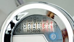
Positive displacement meters included nutating discs that wobble around a fixed axis as liquid flows past the disc. The axle of the rotating disc is connected to gears which mechanically register flow quantities by turning linked display wheels that show the quantity of accumulated flow. Piston meters utilize a cam with a known volume as a measurement chamber. The motion of the piston is also transferred to mechanical gears and an analog display. Gear and lobe meters rely on “pinching” known volumes of liquid between entrapping gear teeth. A version of this is a helix meter that uses a pair of radially enmeshed helical gears to provide measurement by displacement.
Some types of pumps can effectively self-meter themselves utilizing their own mechanical movements. These include diaphragm pumps, piston pumps, and peristaltic pumps. What these all have in common is a cycle of movement that displaces and moves a fixed amount of liquid with each cycle. Peristaltic pumps have a fixed segment of flexible hose squeezed by the movement of cams along its length, with each such movement displacing the same amount of liquid. Piston pumps do the same with a fixed amount of liquid filling a piston and refilling it with each stroke of the piston. The vibration of the diaphragm also moves a fixed quantity of liquid. By counting the number of movement cycles in a given duration and knowing the amount of liquid displaced with each movement, an operator can measure the total amount of liquid being pumped in a given time period.
While each of these mechanical methods is still in use, the methods are typically modified to allow for digital measurement display and electronic data logging. Intermediate between mechanical metering and non-mechanical methods are pressure-based meters. These rely on Bernoulli’s principle (the speed of a fluid occurs simultaneously with a decrease in its pressure) to indirectly measure flow velocity by measuring pressure differences along the direction of flow. These come in a multitude of configurations (venture, orifice plate, pitot tube, cone meters, etc.) depending on the liquid being measured and the configuration of the discharge system.
Purely non-mechanical flow meters utilize neither mechanical movement nor pressure differentials to measure flow rates. Instead, they utilize measurement of the effects of fluid flow. These include thermal mass, vortex disturbance, sonar measurements, ultrasonic readings, laser Doppler measurements, and electromagnetic flow readings. Thermal mass meters measure the difference in induced heat transfer as fluid flows past the meter. Vortex meters measure the vortices induced by an obstacle placed in the path of the fluid flow. Sonar meters can be clamped onto the outer surface of any pipe by measuring the speed of sound through the liquid, which can vary with the velocity of the liquid. Magnetic meters measure the potential difference via magnetic induction across a liquid flow, which also varies with flow velocity. Ultrasonic meters use the Doppler effect by measuring ultrasonic transfer time through the fluid. Lastly, laser Doppler flow meters measure the wavelength of a beam of laser light reflected off of a particle in the fluid, with the wavelength being proportional to the speed of the fluid flow.
The pump’s performance curve arcs downward from a high point of maximum operational head and zero flow rate to a point of minimal head and maximum flow. Pumps essentially become more efficient with increased flow rates. Conversely, the operating head curve arcs upward from the graph’s zero/zero point (no head and no flow) to a point of both maximum head and maximum flow. Where the two curves cross is the point where the pump will operate. At its most simple, pump control involves adjusting the point where the two curves cross, either by altering the discharge operating systems or by adjusting the pump itself.
Basic pump control involves one of four methods: throttling, bypassing, variable speed drive, and simple on/off control switches. All involve altering the effective speed of the pump. Throttle is the most common and simplest means of adjusting a pump operation. In effect it is not the pump speed itself that is being affected, but rather the discharge valve, which is partially closed. What this change in system head does is to increase the pump system head losses, altering where the pump is operating on its performance curve and thus, its effective speed and discharge. Less common is the bypass control, which is primarily used in circulation pump systems where variable amounts of the pumps discharge is bypassed to the pump’s suction. A variable speed drive adjusts the operation of the pump itself. Decreasing or increasing the pump’s operating speed will move the pump’s performance curve downward or upward respectively. By sliding the pump upward, the curves’ new crossing point results in both increased flow and head while sliding it downward does the opposite, in a very energy efficient manner. Lastly, where pump flow does not need to be gradually adjusted, the pump can be simply turned on or off as needed.
The methods used by pump controllers and their specifications result in various categories: proportional/variable controls that require continuous feedback between the pump and the controller, limit controls that operate in a binary fashion to turn a pump completely off when its performance exceeds its required operating parameters, and linear controls that vary the pump’s performance either by directly modifying the pump’s speed or its discharge system characteristics. More advanced systems utilize complex computer software and algorithms that in effect make decisions based on multiple performance variables and can control multiple output functions. The human operator can interface with the pump controls via several different types of platforms. These include simple needle gauges, digital readouts, mechanical controls (knobs, buttons, and switches), computer keyboard and computer screen displays, and internet-based web systems.
OVERALL SYSTEM CONTROL AT A DISTANCE: SCADA
Even the most advanced monitoring and control system needs to have a human in the loop. But that doesn’t necessarily mean that a human has to be physically present. That is where SCADA (Supervisory Control and Data Acquisition) comes in to play. This advancement in the art of operational control allows the operator to monitor the system from a remote location.
SCADA does double duty. It gathers real-time data on the operations of hydraulic, mechanical, heating, and electrical systems. And it simultaneously allows for remote control of these same systems (though some SCADA systems only provide data gathering and monitoring). Control can be exercised from a remote central location or distributed operating nodes. The resultant network creates an information and data feedback loop consisting of three steps. Data from current operations get sent to the control center. This data is then used to guide changes and modifications to current operations in order to optimize the performance and efficiency of these operations. The control center then transmits instructions to make these operational changes. This in turn creates a new set of data to be sent back to the control center where further adjustments are made and transmitted.
The remote monitoring capabilities provided by SCADA allow for managerial decision-making, as well as operational changes. Whole system performance can be evaluated by accumulating data from different sources within the operating system as well as external systems that are being acted upon by the primary operating system. Water usage for boiler and heating operations can be coordinated with the supply of a building’s drinking water; water storage for fire control; water used in landscaping; and water supplied to multiple sinks, fountains, and toilets. Tracking usage trends will allow a water system manager to allocate his available water supply accordingly, minimizing both waste and costs.
FUTURE TRENDS AND TECHNICAL POSSIBILITIES
Artificial intelligence (AI) and “smart” systems are the next generation of water system controls. Monitors and controls already talk to each other, and soon they will be able to have whole conversations. Early artificial intelligence programs were “expert systems” that made decisions based on a fixed number of relatively simple rules. While a major advance for its time, this early AI proved too rigid and clumsy for the management of constantly changing dynamic systems with multiple inter-acting feedback loops, such as a community water system or the water supply operations of a major hospital.
More advanced AI algorithms provided much needed flexibility adaptability and even the ability to learn over time. Using pattern recognition, advanced AI automatically updates its weighting factors and transfer functions with each new batch of data. In this way, AI can mimic human learning patterns with changes to its analytical factors creating new patterns that it can recognize. These patterns are constantly changing and evolving during the schooling phase of AI application. This makes AI essential in the management of large water supply and distribution systems and for ensuring the highest possible levels of cost effectiveness and efficiency.
Armed with this information, the human managers of the water distribution systems can make informed decisions concerning capital project needs and annualized maintenance costs. In addition to water use data, population growth projections and economic forecasts can be combined to create an overall long-term planning function for a water utility.
The sensory organs of the AI “brain” (its “eyes and ears”) are the sensors deployed at key locations throughout the water distribution network. These can include noise sensors to detect leak locations, pressure gauges, flow meters, temperature gauges, etc.—all of it digital, all of it interconnected, all of it talking to each other—and without a single moving part. Expanding such an information system to include storm drains, sanitary sewers (and waste water treatment operations), ground water aquifers, pumping operations, and the storage capacity of above ground reservoirs is the next logical step in creating a truly integrated “smart water” management system.
And since even public utilities have a bottom line and budgets to meet, the end goal is to allow for the intelligent application of financial resources to maintain and expand the water supply system to meet current and projected needs. Cities and corporations have limited operational and capital budgets, so every penny counts. Instead of making guesses based on vague information, operators will be able to use integrated hard data to guide precise allocations of funds while improving customer service in the form a prompt and accurate billing, along with reduced costs.
Yet innovation and vision remain human traits. Not everything can be done by a machine. In a world of ever increasing urbanization and a world-wide population heading north of 9 billion people, every drop of water is precious and must be accounted for and used with maximum efficiency. Digital smart water will make this possible.
MAJOR SUPPLIERS
Blue-White Industries has manufactured chemical metering pumps and flow meters since 1957. The technology they employ ranges from mechanical BW DIGI-METER Paddlewheel Flowmeters to the SONIC-PRO Ultrasonic Flowmeters. The Paddlewheel Flow meters are battery or electrical powered and are used for measuring flow rate, total flow, analog output, batch processing quantities, and for providing a flow rate alarm. Their applications range from the Micro-Flo model, measuring only 30 to 7,000 milliliter per minute flows, to the F-2000, handling flows from 0.4 to 8,000 GPM. The SONIC-PRO Ultrasonic Flowmeters have no moving parts, instead utilizing hybrid-Doppler and transit time measurements based on sound readings. As such, it can be mounted on the outside of pipes ranging in size from 1⁄2 inch to 100 inches in diameter.
E/One control systems utilize a modular approach, combining both control systems and monitoring functions on a single skid-mounted unit. Their Gas Station modules provide a wide range of functions beyond simply measuring flow rates. In addition to operating the main gas supply manifold and associated control systems, the Gas Station module monitors gas purity and dew point, guards against overheating, performs gas drying operations, and monitors both seal oil systems and partial discharges. E/One systems minimize upfront capital costs as well as later installation and maintenance costs. While managing a gas system for a power utility and other independent power suppliers, E/One provides accurate real time data to the operator. Special hazardous area designs are also available. Their GGA/AUX 2-Mod Gas Station provides both gas purity monitoring and additional site-specific monitoring functions as required. It meets international standards for hazardous area deployment and can be configured as an open-frame or NEMA 3R. Its GGA microprocessor is controlled with self-diagnostic programs measuring differential and case pressures dual gauge and dual transmitters.
Grundfos Pumps come with a variety of controls and monitoring systems for their pumps. These include dedicated communication and transmission modules for complex pumping operations. Their systems include open protocols and data collection options that can be modified to be fully compatible with an operator’s overall system. The Grundfos PC software package monitors operations, makes adjustments to settings, and saves logged flow data—all from a personal computer. An example of this approach is the CU331SP, a drive program with settings optimized for submersible pump operations. It is ideal for use in domestic and commercial water supply operations, irrigation and livestock watering, and water transmission. It works with any Grundfos matched paring of pump and motor. It works with 2, 3, or 5 horsepower submersible pumps and matching motors. It can be installed with indoor or outdoor enclosure options and is further protected by over/under voltage, sensor alarm, and alarm relay systems.
Smith & Loveless provides simple and rugged pumping solutions provided by its QUICKSMART Station Controls. This system gives an operator the ability to monitor and modify all pump station operations. Its design simplicity allows for ease of use with an intuitive layout and organization of its control screen. Its maintenance log feature provides ready access to lubrication and maintenance needs while suggesting the proper time of lubrication depending on actual pump run times. The I/O status screen provides needed information for troubleshooting and repair.
helped optimize system efficiency
Xylem/Flygt emphasizes simple waste and sewage water flow control. Simplicity makes for easy oversight while providing at-point profiles that let an operator optimize pump station operations. A thoughtfully designed and intuitive interface makes operating simple with pre-supplied default settings. Digital control is provided by MultiSmart, which allows an operator to adjust working parameters in order to maximize operational efficiency. This includes simple set-point adjustments to complete alterations for large pumping systems. While providing information for preventative maintenance, MultiSmart allows for remote switching of start times and durations for a multitude of specific tasks. It comes with costs saving features such as pump reversal to prevent clogging and spill management. It can manage pump electrical energy usage while achieving further operational cost-savings with an efficient three-phase current monitoring function. A built-in SCADA system eliminates the costs associated with HMI hardware and software.
Vaughan Company specializes in water heaters and controllers as well as their control systems. Specifically, it has provided energy controllers, programmable controllers, and digital timers for over 30 years. High-quality energy controllers are designed for use with electrical thermal heat storage facilities. The programming of these units meets stringent standards set by utility companies. Operation efficiency is combined with flexibility, allowing the system owner to override the system and operate it manually with the push of a button.
For 49 years, Thompson Pump & Manufacturing has been a full-service manufacturer of dewatering pumps and associated pump equipment. They provide advanced control panels such as the RECON2000T. It uses smart technology that allows for remote monitoring from a variety of platforms (personal computer, laptop, or smart phone). It does so via secure connections over cellular and satellite networks and comes Wi-Fi ready. Remote operators can start and stop the pump at any time, while varying speed and recording all associated pump operating data. The data is conveniently displayed in the same manner on both the onsite control panel and the remote-control dashboard.
Evoqua is an industry leader in pumps and pump controls. The company’s IONPURE Products provide digital communication rectifiers (DCR) that allow for remote control of continuous electro-deionization modules (IONPURE MX, LX, VNX CEDI, and NEXED EDR). These are ruggedly built and reliable single-phase DC power controllers based on an advanced microprocessor technology. Its built in digital communications system with MODBUS or 4-20mA signals make for easy integration into established PLC/HMI systems. Evoqua’s new DC3 power supply for its modules operate with microprocessor-controlled DC power and MODBUS TCP communication systems.
