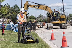
Many popular sayings are polar opposites of each other. “Look before you leap” is the exact opposite of “He who hesitates is lost.” However, a successful earthwork contractor must do both simultaneously. They must avoid the hidden dangers that can lurk below ground at any job site. They must also perform his work in an expeditious manner at maximum efficiency in order to get the job done in the first place and then show a profit. So how does a contractor accomplish two contradictory goals at the same time? He does so by using the advanced technology of underground utility detection and location systems.
Every urban earthwork job—and most jobs in every other location—presents a minefield of potential dangers to the excavator, trencher, and earthmover. These are old and abandoned, as well as new and active, buried underground utilities: electrical power lines, communication wires, storm sewers, sanitary sewers, water mains, gas pipelines, etc. These utilities may be located on reasonably accurate site maps and utility plan and profile drawings, but no contractor can rely solely on written records—especially if those records are old and outdated. And not every existing utility will appear on a convenient map. In fact, many old utility locations were never recorded at all, or if they were, the paper, mylar, or microfiche survey drawings and field notes have long since been lost.
Just because a utility is no longer active does not mean that that it no longer poses a danger. Buried pipelines can be abandoned in place, sealed off at both ends, yet still contain significant amounts of dangerous gases and liquids. This is especially true at old, abandoned industrial sites that predate the enforcement of strict environmental controls and regulations. An old, abandoned gas pipeline could still contain explosive levels of methane. Abandoned industrial sewers could contain significant amounts of toxic chemicals. Active or abandoned, a buried utility presents potential danger to the excavation contractor. To protect themselves and to improve the efficiency of their operations, contractors rely on various types and applications of subsurface detection and location technologies.
Types of Subsurface Detection Technologies and Methods
What does utility technology have to do? Who uses this technology? Utility contractors, construction professionals, environmental engineers, site investigation teams, and land surveyors need an easy-to-use, reliable, and non-destructive method to locate subsurface targets prior to digging, trenching, conducting site assessments, tunneling, drilling, mapping, performing groundwater assessments, repairing existing utilities, or adding on to utility systems.
Most older pipes are typically made from cast iron, while newer service lines are often made from copper or other metals. This is an obvious situation for the use of magnetic detection technology. This method is used to locate and detect metallic utilities of various types (conduits, pipelines, power cables carrying an electric current, and communication lines transmitting a signal). Magnetic induction is a process of inducing magnetism in a non-magnetic piece of metal and can be used to make steel and iron into magnets. Magnetic induction involves placing a magnet strong enough to induce magnetism close to but not touching the metal object. As a result, the metal object becomes an induced magnet with opposite polarity than that of the inducing magnet. The effects are temporary—the metal object returns to its initial non-magnetic state once the inducing magnet is removed.
This effect explains one of the odd things about using magnetic detection to locate metal pipes and utilities. The strongest signals received from the metal pipe occur at the ends of the pipeline, where the magnetic force lines concentrate and are more easily detected. This same concentration of magnetic force lines also occurs at wye joints, tee joints, valves, and cleanouts located along the pipeline. Therefore, it is often easier to detect individual buried objects that are vertically oriented (like a buried steel drum or casing) than it is to detect a horizontally laid out metal pipe system. In any case, it is a function of the strength of the magnetic field and the depth below ground surface of the metallic utility or object. Increasing the strength of the magnetic field or finding utilities at shallow depths will increase the potential for finding them. In the field, finding a buried metal utility alignment can consist of “connecting the dots” between peak signals that appear at the ends and joints of the utility network. Once the location of these peak signal points can be determined (establishing their northing, easting, and elevation values), the utility alignment and depth between these points can be determined.
Getting an aerial view with Google Earth
As mentioned above, other metallic utilities can be found utilizing magnetic detection, not just metal pipelines. These include electrical power lines that are either operating and carry an electrical current (and thereby create their own detectable magnetic field), or are abandoned but can have an electrical field directly induced by means of an applied electrical charge. To directly induce an electrical field on a utility, the operator can attach a low-voltage electrical power source (usually an easily portable battery) to the known ends of the utility. A strong current then travels the length of the utility, giving off an equally strong electric field. The increased strength of the electrical field allows for easier detection over greater lengths and at greater depths. This method can also be used for metal pipes located at depths that are ordinarily too deep to detect.
Tracing out the line of the buried utility in the field is not unlike old-fashioned dowsing. The operator walks along the alignment of the pipe or cable and hears a louder audio signal, which fades as the operator moves off of the alignment. To determine the peak audio signal, the operator can walk at short distances perpendicular to the assumed utility alignment. As he approaches the utility, the audio signal increases until it peaks directly over the utility and then fades as he passes over and beyond its centerline. The low baseline audio signal (indicating that the utility is not located underneath) is typically set at 40 Hz. Noting the location where the audio signal peaks by marking the location on the ground surface with chalk provides a field reference of its location. These visual markings (annotated with survey information, type of utility, and measured depth) can then be used to guide subsequent trenching and excavation operations. A derivative of the magnetic location method is the determination of buried electrical powerline locations by measuring voltage differential in the overlaying sol strata.
However, magnetic detection is only useful for finding metallic objects and utilities. Many utilities are made of plastic piping or concrete sewers. So, another technology is used to find non-metallic (as well as metallic) utilities: ground-penetrating radar (GPR). By utilizing an electromagnetic antenna broadcasting radio waves into the ground at frequencies that can penetrate pavement, rock, and soil, an operator can locate other types of buried utilities. This system is designed to locate and penetrate both natural materials (such as rock, ice, and frozen ground) and manmade materials (utilities, concrete foundations, etc.) over a much broader swath than the more narrowly focused magnetic detection method. This method allows for the determination and mapping of both local geotechnical conditions as well as manmade utilities. However, GPR tends to take longer to perform its readings and process the data it receives, and typically costs more than magnetic detection. Therefore, GPR tends to be utilized more often in sparse rural areas with few buried utilities instead of in crowded urban environments.
GPR’s operation is not much different than that of standard radar used to detect aircraft at far distances. High-frequency antennas (1000MHz–2.6GHz) are often used for detecting concrete foundations, footers, and abutments. Low-frequency radar is used to detect utilities. In general, the higher-frequency radar has less penetration but returns higher image resolution and provides more data detail. Each sends out high-frequency radio waves at regularly timed pulses. When these radio waves hit a flying aircraft or a buried object, they bounce off of its surface back toward its broadcasting unit where it is intercepted by a receiving antenna. Those radio signals that do not strike a solid object continue on through the atmosphere or the soil until they fade out or encounter something farther away (or farther down). It is this ability to pick up multiple objects with one signal that makes GPR so highly efficient.
Radio signals can also be partially deflected, which allows them to define the locations of changes in groundwater, voids and fractures in the soil, and differing soil types. At standard operation setting, GPR can provide accurate renditions of underlying soil and geotechnical conditions. The more sensitive GPR models can also accurately locate and define the depths and alignments of various utilities.
Some utility detection and location technologies do not require the broadcast of radio waves or magnetic fields. These are passive sound detection devices that detect sounds far below the ground surface. This method is of special importance if there is a need to accurately locate a part of the buried utility—typically leaking water supply pipes with water escaping under high pressure—that needs repair.
Since the water in a water supply pipeline is under significant pressure, water escaping through a leak spurts out at high velocity and makes a hissing sound while doing so. The ground microphones used by passive sound detection devices can detect these sounds at considerable depth. These sound vibrations can travel down the length of the body of the pipeline for a significant distance, allowing the passive sound detection system to trace it back to its point of origin at the leak. Like magnetic detection technology, the signal gets louder as the operator gets closer to the source, though in this case, the sound is actual noise generated by the leak instead of an audio signal created by increased magnetic response. So, the noise gets louder upon approach to the leak location and decreases as the operator passes beyond. This peak noise determines the location and depth of the leak.
When trying to determine if a leak is located between two known points such as shut-off valves located along a water pipeline, passive noise detection can be augmented by the use of magnets. When using this method, the operator attaches a pair of spring-loaded snap lock-type pliers to both of the water valves. A magnet is then attached to both pliers. The water-leak noise will transmit through the pipeline, valve, pliers, and magnet into the passive sound sensor from a depth down to 6 or 8 feet and at a distance up to 50 feet. By using this technique, the detection system operator can isolate the location of the leak quickly to a point between the bracketing valve locations.
Data-Recording Methods and Procedures
Each site will use at least one of these techniques to determine buried utility locations, depths, and alignments. More complicated sites, depending on the location, may end up using all of them. The next step is to properly record and display this valuable information. Even in this high-tech age, manual recording of field data remains important. This is performed in field manuals, but most importantly, the data is drawn on the ground itself. These marks are in chalk or spray paint, color-coded, and easily visible from the operating cab of a heavy piece of earthmoving equipment. In addition to lines showing the direction and alignment of the utility underneath, the markings can include numbers and words providing direct data and information concerning the type of utility, its depth, etc.
Electronic data is also recorded and stored by Location Data Recorders. The field data is initially generated by the detection methods utilized for the site investigation, and then digitally recorded in an extensive and sophisticated GPS-computerized database. The data recorders include both auxiliary field computers and direct storage in the GPS survey equipment itself. The goal is to create a three-dimensional drawing in CADD or BIM that shows all aspects of the site’s underground environment: the existing terrain surface elevations (usually displayed as contour lines and spot elevations on a TIN model surface); the proposed terrain surface elevations that result from the planned earthwork operations; the depths and alignments of exiting utilities of all types; the proposed depths and alignment of the utilities to be installed; existing geotechnical and groundwater information; buried structures and foundations; buried manmade objects; surface hydrologic features such as ponds and rivers, property lines, setbacks, and easements; existing and proposed pavement locations and thicknesses; roads and railroads; and any overhead structures that could interfere with earthwork operations. This last item is often neglected, and proposed excavation plans to avoid underground utilities may be nullified by the existence of dangerous overhead power lines that make excavation impossible for safety reasons.
And while even sophisticated utility information can be displayed with painting marks on a ground surface, most earthwork operations are now directed by equipment GPS systems. This allows the direct connection of a utility detection system to the GPS unit, or for its accumulated field data downloaded to the same. The GPS system can then produce 3D images of the site’s underground condition directly to the screen in the equipment operator’s cab. Information from the sensors attached to the dozer blade or bucket teeth of the excavator can be used to continuously update this data—and its 3D screen display—in real time as excavation operations proceed across the site. The excavation and earthwork will be guided by proposed CADD design surfaces that have been downloaded into the GPS guidance system and superimposed on the CADD survey of the existing terrain. As each new utility line is discovered and exposed during excavation, additional field surveys can be performed to directly measure their locations along with the locations of any leaks and repairs.
Sources of Error: The Impact of Job Site Locations and Ground Conditions
A typical earthwork site, especially in urban environments, is a complicated place. In addition to existing utilities, soil types and characteristics, surface topography, and groundwater elevations, there is an abundance of discrete, manmade structures. These include foundations and abutments, buried objects (even debris and trash), and pavements of various types and thicknesses. The presence of other utilities in close proximity can interfere with the detection of the utility in question. Technology also imposes limitations. Magnetic detection, for example, cannot be used to locate non-metallic utilities. Unless a water or gas pipeline is actually leaking, passive sound detection is not applicable. All of these site conditions can affect the accuracy and completeness of the underground detection effort and survey. But the most complicated set of limitations comes with the use of GPR.
One is a shadowing effect produced by large objects. And it is not just solid blocks of concrete or large rocks that can create a shadow. Natural soils, such as high-conductivity clays that have been permeated with salts, can severely impact the performance of GPR. Conversely, many smaller objects, such as a multitude of gravels imbedded in rocky soil, can scatter the radar signal. Further limitations may be imposed by a lack of sufficient power to operate the radar system. Weak signals have limited penetrating power, and excessive electrical energy may be required for proper functioning. In order to detect changes in material composition, the radar has to be moved to display these differences, which aren’t apparent from a stationarity reading.
Environmental conditions affect high-frequency and low-frequency GPR differently. Moisture is the most reflective material encountered by radar. So, in concrete that has not yet been properly cured, greater reflectivity would make it difficult to achieve full penetration and acquisition of complete data. The electrical conductivity of the ground can also inhibit high-frequency radar and limit its depth of penetration. In addition to the types of soils, the types of utilities may be difficult to ascertain using only GPR. Low-frequency radar has an easier time locating conductive materials like metal pipes since they have greater reflectivity (though radar can also detect empty PVC pipes).
Accuracy and ability to locate buried objects varies with depth. In general, for every foot that an object is buried below ground surface, its minimal dimension (diameter) relative to the direction of the radar signal has to be at least 1 inch in order to be detected. For example, a buried 55-gallon drum oriented vertically with a diameter of 22.5 inches can be detected at a depth of 22.5 feet. With a length of 33.5 inches, it could be detected at a depth of 33.5 feet, provided that it was lying on its side and oriented properly to the direction of the radar signal.
In addition to missing objects that are there, a false-positive reading that indicated the presence of a non-existent object is also possible. An experienced operator can judge these miscues or avoid them entirely. And this is where most false positives originate: operator error and misreading of the data. A significant amount of experience and extensive training are required to properly read and interpret GPR imagery. Though there are inherent limitations on the use of utility detection based on site conditions and the technology itself, the primary source of error is human error.
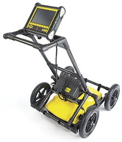
The LMX100
Major Suppliers
Geophysical Survey Systems Inc. (GSSI) is a worldwide leading manufacturer of the UtilityScan line of ground-penetrating radar systems. Its UtilityScan and Profiler EMP-400 combines accuracy and ease of use. Using these systems, construction professionals, utility locators, and engineers can locate the depth and position of metallic and non-metallic pipes (including service utilities such as gas, communications, and sewer lines, as well as underground storage tanks and PVC pipes) in real time using the GSSI UtilityScan. The UtilityScan Pro features the SIR 4000 control unit which is configurable to provide maximum flexibility for a wide range of utility applications. UtilityScan DF incorporates our innovative, digital dual-frequency antenna (300 and 800 MHz) and an easy-to-use touchscreen interface to view shallow and deep targets simultaneously in a single scan. With an operation life of up to eight hours and a survey speed of up to 6.25 miles per hour, data collection is fast and efficient. The UtilityScan features a wireless and lightweight configuration, a patented HyperStacking technology, and integrated LineTrac system. The SIR 4000 is GSSI’s first high-performance GPR data acquisition system designed to operate with analog and digital antennas. It incorporates advanced display modes and filtering capabilities for “in-the-field” processing and imaging. Fully integrated, the system provides a simple user interface, plug-and-play GPS integration, and convenient data transfer options. The SIR 3000 is a small, lightweight system designed for single-user operation that incorporates advanced signal processing and display capability for “in-the-field” 3D imaging. It is interchangeable with all GSSI antennas. The SIR 30 is the next-generation, high-performance, multi-channel radar control unit. This system can collect up to eight channels of data simultaneously. It offers advanced filters and display capabilities for real-time processing, including migration, surface positioning, signal floor tracking, and adaptive background removal.
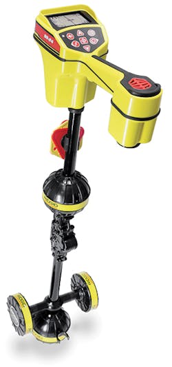
Ridgid’s SR-24 and RIDGIDtrax app
Enviroprobe Service Inc. is a user of GSSI equipment. It offers a full line of non-invasive subsurface geophysical surveys to assist our clients with collecting and analyzing data to help assess various needs. Enviroprobe offers geophysical investigation services for delineating utilities and underground storage tanks (USTs), identifying potential subsidence or sinkholes, scanning and delineating anomalies embedded in concrete, mapping contamination/plumes, delineating landfills, etc. Enviroprobe’s geophysicists and geophysical technicians use a variety of geophysical equipment to map the subsurface in real time. This high-resolution mapping is invaluable for locating utility lines and USTs when drilling or geoprobing in the area; however, geophysics can be useful to answer a wide array of geotechnical questions. For a small business like theirs, cost is of major concern when acquiring new equipment. In the past, Enviroprobe Service has used a variety of GPR units to cover a broad spectrum of services with options to achieve the best results with equipment that may be more suited to particle job sites or conditions. These units ranged in cost from $15,000–25,000 on average from at least three different manufacturers. They now have three UtilityScan units and use them daily to mark utilities, USTs, excavation, septic systems, tunnels, foundations, and so on at depths of 0.5 feet to 20 feet below ground surface (BGS). The increased achieved signal penetration is by far the most significant advantage in utilizing these new devices. They routinely achieve 50–100% more penetration than with units used in the past. Adding to that the advantages of being able to correlate data with our pipe and cable locator and the LineTrac feature, while actively identifying passive signals during out GPR investigation, their successes in identifying anomalies and efficiency onsite significantly improve as well. The tablet based interfaces are very user-friendly and intuitive whether for someone familiar with GSSI software or just a simple smartphone.
For over 90 years, McLaughlin has been a leading member of the boring and excavation industry that provides a full range of utility locators. The Vermeer Verifier G3 by McLaughlin combines precision with a simple, user-friendly interface. The Verifier G3 is designed with durability in mind, with antennas mounted in rubber isolators to stand up to tough job site conditions. Its Vision FLX2 by McLaughlin combines a state-of-the-art fault location system with a dependable and accurate cable locator. It offers cable tracing with depth estimate and pinpoints ground return faults on electric, CATV, and telecommunications with one instrument. The McLaughlin GX is a utility locator designed with three locating modes: peak mode with manual gain adjustment; peak mode with semi-auto gain adjustment, which narrows the peak signal for easier identification of utilities in congested areas and deep utilities; and combination peak-and-null mode for quick detection of the transmitted signals.
Sensors & Software is a leading manufacturer of GPR equipment. During its 30 years in business, it has sold equipment in over 100 countries around the world. There are many applications of GPR, but one of the most common applications is finding underground pipes and conduits. “Sensors & Software believes in designing products specific for the intended application,” says Troy De Souza, training manager at Sensors & Software. “The needs of a utility locator are different from an archaeologist, which are different from a geophysicist. Our products are simple to use, reliable, and focus on getting quick results in the field.” To that end, Sensors & Software offers two main products for the utility-locating market: the LMX100 and LMX200.
LMX100 is very popular with utility locators who just need to locate and put paint on the ground. The system is durable and easy to use, yet inexpensive. Operators can turn on the system and begin surveying. As they cross targets on the screen, they can back up the system to locate the exact position and depth of the buried object.
LMX200 is built for the advanced locator; this product offers all the features of the LMX100. In addition, the user can collect grids of data to locate all objects in a given area. This is helpful for clearing a site where there are unknown and abandoned pipes. Data can be downloaded for further analysis in software and report writing.
Recent advances in technology have resulted in more capabilities in the field. These include responsive touchscreen operations, built-in GPS, and Wi-Fi, with the latter allowing the user to email mini-reports (with image) right from the field. These features are standard on the LMX100 and LMX200, and improve the overall productivity of the user. “At the end of the day, it’s about confidently finding all buried objects to prevent damage during excavation. That’s what every manager wants: reliable results in a minimal amount of time,” says De Souza.