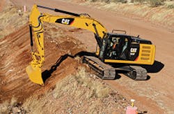
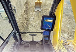
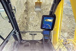
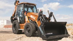
When you add a GPS system, you use the same controls, but you get a display of your bucket location relative to the design grade. How does it all work? Grading and Excavation Contractor sought out answers from several manufacturers, and here is what they said.
Volvo Construction Equipment uses the terminology electro-hydraulic system to describe Volvo controls, says Sejong Ko, Volvo product specialist, excavators. Operators should be able to get information and warning on a monitor easily and in time—and monitors also should be in the cabin where the functions help operators control excavators comfortably and productively. The Volvo interior design and human machine interface (HMI) were designed for that with easy reading of the monitor, well-positioned switches, good space, excellent visibility, and safety features (e.g. guard options, emergency exit, etc.).
HMI is part of the Volvo electro-hydraulic control system, so that operators can easily operate the excavators. The hydraulic pump flow demand is determined by the stroke of the joystick/pedal. Due to the electro-hydraulic control design, the machine response is fast and smooth, and troubleshooting is easier and faster. Pressure sensors are used on the low servo pressure control side as well as on the pump pressure side.
Volvo’s main pumps and servo pump are directly attached to the engine. As the engine turns, servo pump flow is generated to provide oil to the operator controls. Low pressure sensors are used on each pilot function to communicate with the vehicle electronic control unit. The main pump generates flow to be used by the travel motors, the swing motor, and the attachments. The operator sets the work mode accordingly.
As the operator activates a function, servo oil displaces a spool in the main control valve and the low-pressure sensors communicate with the new General Purpose Machine Electronic Control Unit (GPMECU) to tell it how much pump flow is needed. That turns on the main pump to generate flow to supply to the cylinders and/or the motors. The cylinders are used to transform the hydraulic flow to a mechanical function (e.g. move arm, boom, bucket, auxiliary attachment, etc.).
The motors utilize the oil generated by the pump to turn either the travel reduction unit for travel functioning and/or the swing reduction unit to swing the upper structure. As the operator works, main system pressure is sensed by the high-pressure sensors located right at the main pump and communicated to the main computer (GPMECU). The GPMECU communicates instantly with the proportional valves located at each pump regulator to control the pump flow (load).
With GPS, the system works to provide “indicate only” controls on the display and a few sensors are attached on excavators. They are different between vendors but typically, one is attached on the bucket linkage, another on the arm, another on the boom, and another on the base machine. A GPS and laser receiver can be added, if needed, to locate, comparing to the reference level or location. They are used to calculate and locate the tip of bucket on the excavator so that the system’s monitor can show the tip’s location, and the operator doesn’t need to rely on other workers when digging or leveling without repeating.
An additional monitor is usually needed and installed in the cabin. More systems use wireless between the monitor and the sensors so installing an aftermarket control system gets easier than before. Or, customers can more easily remove the system from an excavator and install it on another excavator, when needed.
“As far as I know, automatic control is not available in the market,” says Volvo’s Ko. “Some manufacturers may be researching that now or waiting until the market is large enough.”
CASE’s Pilot Control System
CASE-branded excavators use a pilot controlled system to control the bucket function. From the seat of the cab, the operator will use the joysticks that will stroke the bucket spool in the main control valve. This will open or close the A and B ports on the control valve. Once the valves are activated, hydraulic oil heads down the hydraulic lines towards the bucket, causing it to open or close pending on the type of joystick movement from the operator. In addition to these features, we also monitor the amount of oil headed to the boom, arm, and bucket through pressure sensors. This allows us to make sure we have the correct distribution of oil to the attachment based upon the operator’s actions.
“For excavators, the pilot control system is better than the electro-hydraulic process because it gives you better sensitivity for precision applications,” says Philippe Bisson, brand marketing manager, CASE Construction Equipment. “For example, if you’re doing underground pipework, you need to have precise knowledge of your bucket position and movement. Pilot controls allow for greater feel of your attachment and its movements.”
Leica’s Explanation
Machine control doesn’t change the way the operator operates the machine. The operator still controls the bucket—it moves it left and right, in and out, and opens and closes it. What’s different is that that with machine control, the operator knows how deep to dig, says David Rowlett, regional manager for Leica Geosystems Machine Control. Without it, the digging has to periodically stop so that the operator or another person onsite can drop a giant yardstick-like pole down into the hole or trench to see how deep it is, and use a locating laser to measure the depth.
All excavator systems are indicate-only, says Leica’s Rowlett. Automatic operation only exists in grading machines today; it doesn’t exist on excavators.
“With a 2D machine control system, which is the foundation of all Leica Geosystems’ machine control solutions, we first do a careful measurement of the machine components using a highly accurate iCON robotic total station to identify where the bucket teeth are in relation to the other parts of the machine,” says Rowlett. “We then attach sensors to the boom, stick and bucket that tell the operator where the bucket teeth are at all times. The 2D system is a relative system—the operator has to touch a known elevation or laser and then tell the system how deep to dig relative to that point, and the system gives him feedback about how deep he’s digging and whether he’s on the desired slope. Every time the machine tracks move, the operator has to check back in to that known point before he resumes digging.”
Since no machine is ever perfectly level on a jobsite, Leica solutions also use a sensor mounted on the back of the machine that tracks the machine’s pitch, roll, and rotation.
Komatsu’s machine control and guidance system uses hydraulic stroke sensors on the boom, arm, and bucket for precise bucket edge positioning.
Adding GPS creates a 3D machine control system that tells the operator where he is on the jobsite, which way he’s facing, and where the cutting teeth are on the bucket in relation to the design, which has been pre-loaded into the system. If the operator is digging a trench, he can see the trench on the screen even though it doesn’t exist. He can then straddle the imaginary trench in the design and make what he sees on the screen become a reality because the GPS guides him. One GPS antenna is added to the same mast as the pitch, roll, and rotation sensor—usually on the back left corner of the machine—and the other one is added to a mast on the back right corner of the machine. The software calculates from those two GPS antennas on the back of the machine all the way out to the teeth on the cutting edge of the bucket, which might be 60 feet in front of where those antennas are, and it’s accurate to within 1/8 of an inch. This allows the excavator to be accurate to within 1–1/2 inches, which is far more accurate than what can be achieved without machine control.
Machine control provides a substantial safety benefit, because it keeps workers away from the machine while it’s in operation, and it provides a huge leap forward in productivity by taking the guesswork out of the process—the operator can see exactly how deep they are digging while they’re working. GPS takes that a step further in that the operator can drive anywhere on the site and know exactly where he is and how deep he needs to dig. For digging underwater or in any application where the operator is unable to see the bucket, a 3D machine control system with GPS is essential.
Topcon’s Solutions
“GPS provides the operator with two major advantages,” says Kris Maas, product marketing manager, 3D Machine Control, Topcon Positioning Systems. “First, he knows exactly where he is on the site all the time, and knows where to go to excavate certain projects. The second, and even more important aspect, is that real-time grade information is displayed in the cab at all times.”
That is accomplished through a variety of components installed onto the machine, says Maas. System designers need to know the exact measurements of each implement of the machine, and the measurement of the machine body. Individual tilt sensors are placed on the dog-bone, stick, boom, and body of the machine to provide instant attitude information of that specific implement and body of the machine.
Next designers need to know the machine’s real-time position and heading. That is accomplished by placing two GPS antennas onto the body of the machine. All of these components relay their information to the GPS box inside the cab of the machine and real-time machine information is displayed on the control box in the operator’s view. This allows for a constant indication of each implement and the body, and when properly calibrated, the system can tell the operator how far they are away from grade within centimeter accuracy.
Topcon had an automatic control system for excavators over 15 years ago but the market adoption was very small. We see the market demand increasing over the last two to three years in certain applications and some original equipment manufacturers have already begun incorporating automatic hydraulic control for excavators.
Two Types of Sensors
Here, Phil Jackson of Trimble explains how gravity-based tilt sensors and rotation sensors work to help describe to an operator where the bucket teeth are. Start by mounting two global navigation satellite system antennas on masts on the counterbalance where they have the clearest view of the satellites for best performance. This gives a very accurate position, height, and direction for the body of the machine.
Next, add a dual-axis tilt sensor to the body that measures forward-back pitch and sideways roll. This allows the height to be transferred to the boom pin at the front of the body. This also allows the roll of the machine and the correct bucket position when operating on a sideslope to be calculated.
Knowing the boom pivot position, measure the lengths of the boom, stick, and bucket. The bucket tip position can be calculated from the angles of those three components. That is the simple version.
The above describes gravity-based tilt sensors or angle sensors. They have the advantage of being easy to install and calibrate on machines. They calculate angles in terms of gravity, which means that each component is calculated independently from the others, so errors will not be propagated. Some angle sensors have more lag in them than others, so the bucket position may be slower.
Other systems use rotation sensors at the boom pin and stick pin, and a position-sensing cylinder for the bucket. These rotation sensors are very fast and give a relative angle between the two components. This relies on an accurate body sensor, as this angle is propagated all the way to the bucket. The position sensing cylinder measures cylinder length, and then uses the known lengths and geometry of the stick, linkages, and bucket to calculate the bucket teeth.
There are additions and variations to this basic layout. A tilt bucket sensor can be added so that you can work at an angle to the slope.
A single global navigation satellite system receiver can be used, but this usually requires you to rotate the machine every time you move the tracks so that the center of rotation can be used as the second-known 3D point to orientate the machine.
